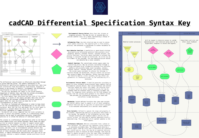
The differential specification is effectively described through a system modeling syntax. The symbols referenced in the differential specification diagram are described here. Note that all information flows described are feed-forward, feedback of state to any process is implicit. Furthermore, the differential specification is laid on a grid where the rows are:
-
The Policies determine the inputs to the system dynamics regardless of whether they come from the outside environment, user behavior or algorithmic decision systems.
-
The State Update Logic determines how the state of the system changes as a result of the inputs provided. Note that not all outcomes are the outcomes intended by the actor (system or agent) when the input decision was made due to the interdependence of these inputs.
-
The State is flattened and summarized in order to keep track of the the interdependence of the mechanisms on the same state variables. Note that the full data model for the state space is generally a network object for which the shown states are mid-level aggregates or summary statistics.
-
The Metrics are values computed from the state variables in order to assess the economic system. In a computational model, metrics may be used for governance decisions, algorithmic policies or to inform the behavior of individual agents.
The columns in a differential specification refer to the Partial State Update Block also called substeps, which break the logic up into an ordered sequence in order to support second order dependencies. For example, there may be a set of user behavior functions that resolve a decision to participate and incur some costs, and then a set of environmental process drivers that determine the rewards those participants receive as a result of all of their decisions and the events which transpire there after. A simple differential specification will have one or two substeps, whereas a complex economic system could have 8 to 10 substeps.
-
Information Flow: Any data structure may be used to convey state update execution. The expected path is from actions, policies, and processes to mechanisms to states variables to metrics.

-
Environmental Process Driver: Data feed that informs an exogenous process. This may be real or assumed data to provide updated input for a model representing a change of external conditions.

-
User Behavior Function: A population or agent-based strategy developed using information gathered from available state variables, metrics, external factors, internal beliefs, and utility functions. The action space available to achieve the strategy is executed through the mechanisms. No action may be fulfillment of the strategy. The user behavior/action should not directly be a state variable.

-
Control Function: The controllable action space under the controlling entity. May be actively controlled through a strategy developed using information gathered from available publicly and privately known state variables, metrics, external factors, internal beliefs, and utility functions. The action space available to achieve the strategy is executed through the mechanisms. Passive control (no action) may correctly model this behavior. Policy functions should not directly modify a state variable, but may affect any parameters in a mechanism as well as the availability of a mechanism.

-
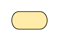
Environmental Process Model: A modelled generator providing an update to state variables using external input signals from an environmental process driver. User action behavior and control functions should not affect this model. The affected state variables should be purely exogenously based, but may be blended from the internal state if necessary to model the system. The exogenous state variables are the link between the changes from the outside world germane to the modeled system, and provides the information necessary for users and controllers to make decisions.
-
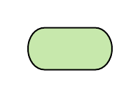
Mechanism: System defined functions that take user actions and control policy input to update a set of state variables. Mechanism functions may be logically or operationally grouped to be executed concurrently as a partial state update.
-
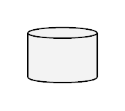
State Variable: Defined to capture the shape and property of the network, representing publicly or privately held output of the system. The updates to the information can only come through mechanisms and exogenous models and not user or control actions. The data may be updated repeatedly within a simulated step. The resolution of all partial updates is the state update.
-
*Performance Indicator: Metrics calculated from a subset of state variables. The indicator may represent actual publicly or privately available data. The metric could also be a computed signal from the state used to determine the condition of a control policy. Also, this may be an expected indicator employed by users to execute on their strategy. Care must be taken to update the metric after the input state variable(s) are updated as to obtain the correct result within a state update.

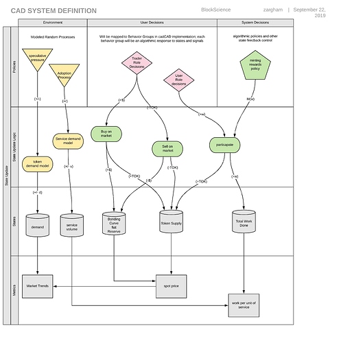
Here is a stylized example of a differential specification for a generic service economy with minted rewards:
